Custom-Shaped Steel Tubes: Design Considerations
What engineers should define before requesting square, rectangular, hexagonal or complex cold-drawn profiles.
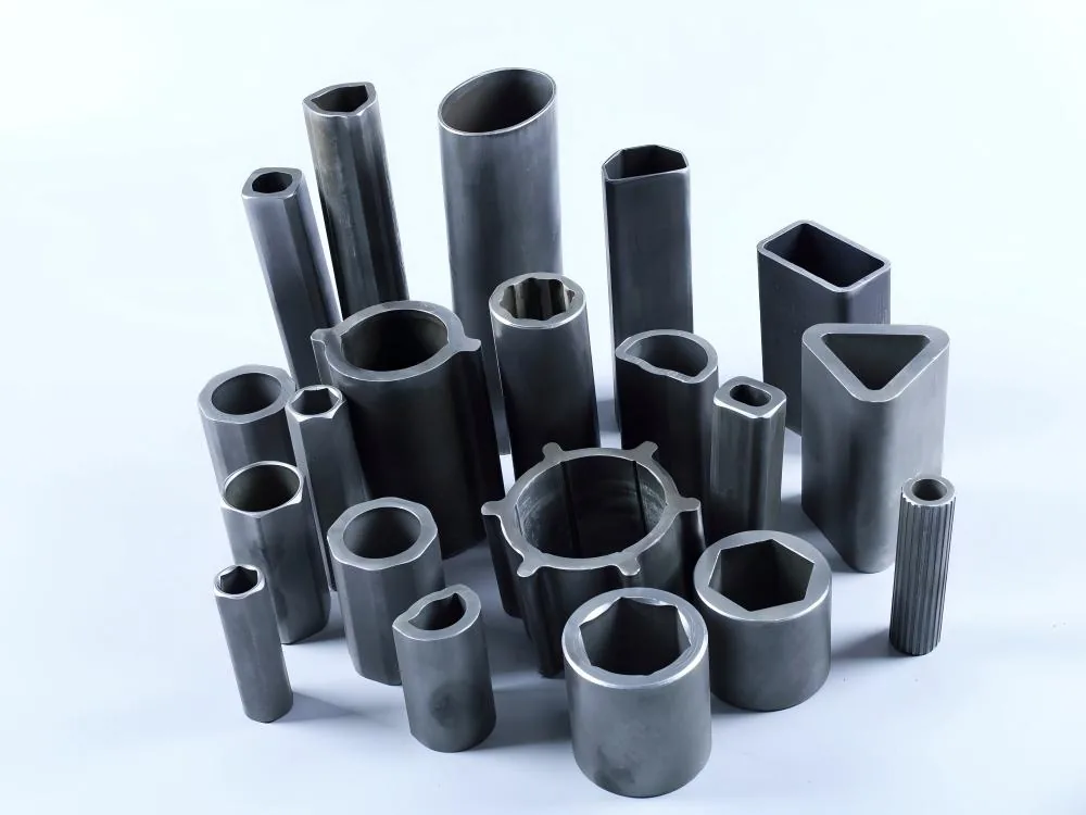
Custom-shaped tubes can reduce machining, simplify assembly and place material where the component needs it most.
Define functional geometry
Identify critical faces, radii, internal features and datum points. Not every dimension needs the same tolerance, so separating functional and non-critical features improves manufacturability.
Plan the production route
Starting tube size, drawing stages, tooling, lubrication and intermediate heat treatment affect the achievable profile and mechanical properties.
Prototype and validate
For new profiles, an initial sample batch allows dimensional capability, assembly fit and downstream machining to be confirmed before full production.
Translate the component function into tube geometry
Begin with the surfaces that locate, carry load, seal or guide another part. Establish datums and identify which flats, corners, radii, bores and wall sections are functional. A drawing that applies the same tight tolerance everywhere is expensive and may still fail to describe assembly needs. Use tighter controls for mating features and realistic allowances for non-critical surfaces.
Choose a practical starting hollow
A custom profile is normally produced from a round, square or other starting tube. Its area, wall distribution and weld or seamless route influence the final geometry. The manufacturer evaluates how material must flow into corners and thin sections during drawing. A profile with abrupt thickness changes, very sharp internal corners or isolated projections may need a revised design, additional passes or a different manufacturing route.
Allow achievable corner radii
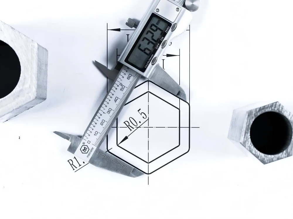
Inside and outside corners are connected by material flow; they cannot be specified independently without considering wall thickness and tooling. Extremely sharp radii increase stress, tool wear and cracking risk. Where the component permits it, a consistent radius improves manufacturability and dimensional stability. Mark truly critical radii and allow the supplier to propose the remaining tool radii.
Control wall thickness and symmetry
Material does not move uniformly around a complex section. Corners, long flats and asymmetric features may show different wall changes. Specify minimum functional wall and critical local thicknesses instead of assuming a single nominal wall will remain everywhere. For asymmetric profiles, identify orientation and the measurement points used for inspection.
Plan for straightness and twist
Non-round profiles require clear definitions for straightness, bow and twist. State the gauge length and datum surface. A long component with tight angular alignment may require dedicated straightening and inspection fixtures. Discuss cut length, end squareness and whether the profile will be machined or welded after delivery.
Material, cold work and heat treatment
Drawing changes strength, hardness and ductility. The required final condition should follow the component’s next operation. An as-drawn profile may provide strength and good dimensional control, while a part that needs significant forming or welding may require annealing or stress relief. For alloy steels, coordinate heat treatment with the section size and final property target.
Tooling and sample approval
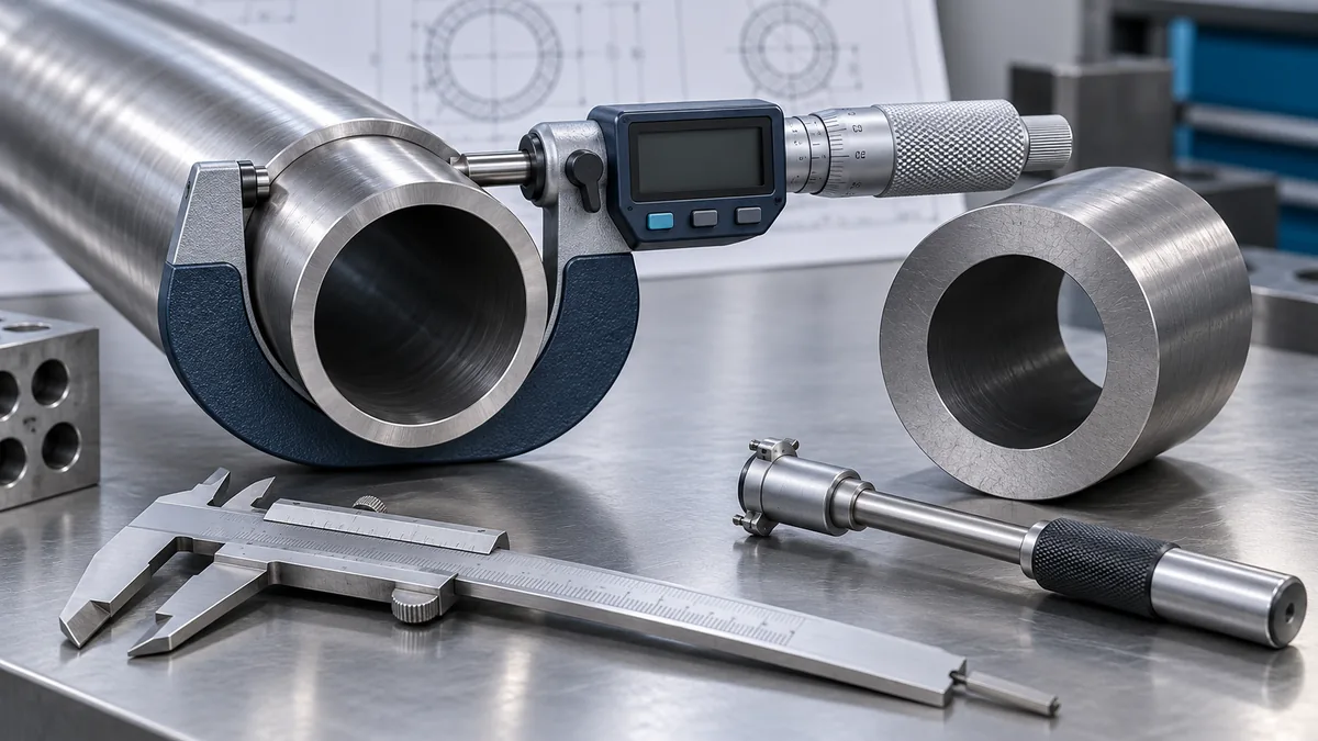
Custom dies and internal tooling should be based on a controlled drawing revision. Before production, agree tooling ownership, maintenance, storage and expected life. Approve first samples using a measurement report and functional assembly test. If a profile is difficult to measure with standard tools, define a checking fixture or scanning method during design rather than after the first lot.
Information for a useful quotation
- 2D drawing and, when available, a 3D model
- Material grade and delivery condition
- Critical dimensions, datums and inspection method
- Length, straightness, twist and end requirements
- Surface, heat treatment and downstream operations
- Annual volume, batch quantity and sample requirement
Explore shaped steel tube options and OEM manufacturing support. Sending the component drawing through the contact page allows tooling and tolerances to be reviewed together.
Frequently Asked Questions
How early should the tube supplier review the profile?
Review it before the component drawing is frozen. Small changes to radii, wall distribution, datum strategy or tolerance can reduce tooling complexity, improve yield and make inspection more reliable.
Is a 3D model enough for quotation?
A model helps explain geometry, but a controlled 2D drawing should define material, datums, tolerances, surface, length and inspection requirements. Both files should carry matching revisions.
Who should own the tooling?
Tool ownership, maintenance, storage, change approval and replacement responsibility should be agreed commercially. The approved sample and inspection record should remain linked to the identified tool set.