Steel Tubes for Engineering Applications: Precision, Standards, and Selection
Engineers specifying steel tubes for heavy machinery, hydraulic systems, or structural frames quickly discover that "standard" is anything but.
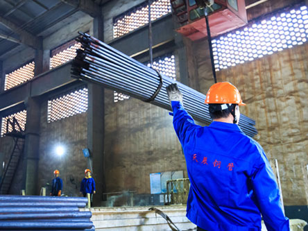
Engineers specifying steel tubes for heavy machinery, hydraulic systems, or structural frames quickly discover that “standard” is anything but. A tube’s dimensional tolerance, surface finish, and end-form shape may not matter much on a warehouse rack, but they become critical when the part must slide into a honed cylinder bore or align with a welded chassis jig. In short, the practical success of an engineering application often hinges on details that generic tube catalogs treat as footnotes.
Why Dimensional Precision Defines Engineering Tubes
When a hot-rolled structural tube arrives with a ±0.5 mm wall tolerance, it might still pass the mill certificate. For an excavator boom pivot, however, that same variation can shift the clearance from a smooth sliding fit to a bind. Engineering tubes, particularly those cold-drawn or cold-rolled, bring the tolerance band down to ±0.1 mm across outer diameter and wall thickness.
Cold-working the steel through a drawing die accomplishes two things simultaneously. First, it size-calibrates the tube to a near-net shape, removing the unpredictable ovality that can plague as-rolled products. Second, it strain-hardens the material, raising yield strength without adding alloy cost. A 0.2 mm wall thickness deviation may sound academic, but in a 108 mm OD cylinder tube that translates to an ID change large enough to alter seal compression and internal leakage rates. Engineers designing telescopic stages or multi-point linkages encounter this sensitivity regularly, which is why DIN 2391 and EN 10305-1 enshrine tolerance classes that cold-drawn tubes can meet and hot-rolled equivalents generally cannot.
Precision also shows up in straightness. A 6-meter tube with 2 mm of bow per meter will introduce assembly stress that cumulative tolerance chains struggle to absorb. Cold-finished tubes, especially those stress-relieved after drawing, keep residual curvature low enough that post-machining operations (threading, grooving, welding) start from a consistent datum.
Making Sense of the Standard Labyrinth
A single engineering project may reference ASTM, EN, DIN, JIS, and GB standards on different drawing sheets. Each standard has its own material designation, testing protocol, and delivery condition, creating real friction during procurement.
Consider two commonly confused pairs. ASTM A519 and DIN 2391 both cover seamless mechanical tubing, but A519 draws its chemical composition from an open menu of grades (1020, 4130, 4140, etc.) while DIN 2391 anchors material to specific steel numbers with fixed hardenability envelopes. ASTM A106 Gr.B, widely used for high-temperature fluid transport, expects a carbon content up to 0.30% and a minimum tensile of 415 MPa. Meanwhile, its European counterpart EN 10216-2 P235GH carries tighter chemistry constraints and slightly different hot-strength ratings. Overlaying these on a shared BOM without normalization can produce tubes that pass one specification but fail the other on a single element.
Correlating standards is not about finding perfect equivalences; it is about identifying where substitution risks lie. For example, JIS G3445 STKM13A is chemically close to ASTM A519 1026 but is tested under different sampling rules. A buyer who orders “STKM13A or equivalent” without qualifying what “equivalent” means (yield, elongation, hardenability band) may receive a tube that machines fine but cracks during cold-forming. We have seen this on a complex hydraulic manifold sub-frame where forming cracks only appeared after zinc plating because the batch met the tensile spec but not the reduction-of-area requirement.
If your BOM spans multiple standards, it is worth mapping the critical performance parameters and confirming which standard drives the acceptance criteria before finalizing the purchase specification.
Carbon Steel or Alloy Steel: Picking the Right Starting Point
The grade selection conversation often begins with the question “Do I need alloy?” The answer depends on what the tube must survive after machining.
Carbon steel grades like 20# (1020) and S45C (1045) cover the majority of static structural and low-pressure fluid-carrying applications. They weld predictably, machine affordably, and respond well to normalizing or stress-relieving. An S355JR structural hollow section, for instance, balances a 355 MPa minimum yield with good impact toughness down to -20°C, making it a frequent pick for mobile crane booms and mining support legs.
Alloy grades come into their own when one of three conditions is present: the component must retain strength above 300°C (boiler tubes), it needs a wear-resistant surface after carburizing (gearbox sleeves), or it must sustain cyclic stress without fatigue crack propagation (hydraulic cylinder rods). In those cases, chromium-molybdenum tubes like 25CrMo4 or 4130 supply the hardenability that carbon grades lack. A 4140 cold-drawn tube, after quench and temper, reaches 900 MPa tensile yet remains machinable in the annealed state, giving the manufacturer flexibility to sequence heat treatment around complex drilling operations.
| Application Stress | Typical Grade | Key Property | Common Standard |
|---|---|---|---|
| Static structural frame | S355JR / St52 | 355 MPa min yield, good weldability | EN 10210, EN 10219 |
| General machinery bushings | 1020 / C22 | Excellent machinability, moderate wear | ASTM A519, DIN 2391 |
| High-cycle hydraulic cylinder | 25CrMo4 / 4130 | High tensile after Q/T, good fatigue | EN 10297-1, ASTM A519 |
| Boiler superheater tubes | 15CrMoG / ASTM A213 T12 | Creep resistance to 550°C | GB/T 5310, ASTM A213 |
| Wear-resistant sliding components | 16MnCr5 / 5120 | Case-hardening, tough core | EN 10084, ASTM A519 |
There is no universal champion. For a hydroformed chassis cross-member, the carbon steel’s formability wins. For a downhole drilling component that cycles from tension to torsion, the alloy’s fatigue limit makes the higher material cost a formality.
Shaped Tubes and Cold-Drawn Profiles: When Round Is Not Enough
Not every application fits inside a round tube. Coupling sleeves, linear guide rails, and locking collars often benefit from starting with the final cross-section already in place, eliminating broaching steps or filler machining. Hexagonal, square, rectangular, and even lemon-shaped profiles can be cold-drawn to a finished geometry that matches the OEM’s envelope directly.
Special-shaped tubes eliminate material waste and reduce machining time because the cold-drawing die delivers the profile and the surface finish in one pass. A carbon steel hexagonal tube for a socket wrench extension, for example, arrives with the six flats sized to ±0.1 mm and a corner radius controlled by the die design, not by a milling cutter. We have supplied octagonal tubes for adjustable linkage arms where the flats act as wrench grip surfaces and orientation indexes, removing the need for secondary broaching.
The same process works for alloy grades. Cold-working a 16MnCr5 or 4140 section increases the as-drawn strength and can reduce the subsequent case-hardening distortion because the grain flow follows the profile contour. If your design already has a non-round cross-section, it is worth exploring whether a cold-drawn profile can replace a hog-out-from-round blank.
Inspection, Certification, and the Truth Behind the Mill Test Report
A mill test certificate (MTC) that reports a yield strength of 415 MPa and an elongation of 22% tells part of the story. The part it does not tell is whether those numbers came from a separately cast test block or from a prolongation of the tube itself. For critical engineering applications, that difference matters.
Full-process quality control starts with the heat analysis of the ladle sample and continues through Positive Material Identification (PMI) on the finished tube surface. Portable XRF or OES spectrometers verify that the tube chemistry matches the grade stated on the traveler card, catching mix-ups that visual inspection cannot. Ultrasonic testing then scans the full wall volume for laminations, slag entrapment, or crack-like indications. For high-pressure boiler tubes, hydrostatic pressure tests at 1.5 to 2 times the design pressure serve as the final gate before shipment, and the acceptance criteria align with standards such as ASTM A450 or EN 10216-2.
Dimensional checks go beyond measuring a few points with calipers. A reliable tube manufacturer uses laser micrometers and air-gauging systems to map the OD, ID, and wall thickness along the full length, generating a data log that becomes part of the inspection documentation. This traceability loop, from heat number to final dimensional report, is what turns a generic tube into an engineering-grade component.
Common Questions About Engineering Steel Tubes
Precision is only necessary for hydraulic or high-pressure systems, isn’t it?
Not exactly. Dimensional precision influences any application where the tube must interface with another machined component. Even a simple structural spacer that slides over a bolt benefits from a controlled ID because the gap affects clamping force distribution. In automated assembly lines, loose-tolerance tubes cause feeding jams that cost more in downtime than the tube itself.
How do I know if a cold-drawn tube has been stress-relieved?
Ask for the delivery condition code on the MTC: “+C” means cold-drawn/hard, “+SR” indicates stress-relieved, “+A” is annealed. A stress-relieved tube will show slightly lower hardness than the hard state but vastly improved dimensional stability during machining. If the MTC only states “cold-drawn” without a suffix, request the heat treatment log.
Can one tube meet multiple international standards simultaneously?
Often yes, but it requires careful grade matching and agreed-upon test parameters upfront. A steel grade such as 20MnV6 can serve both EN 10297-1 and JIS G3441 applications if the melting and heat treatment are controlled to the tighter of the two chemistry ranges and if both sets of mechanical tests are performed on the same heat. This dual-certification approach reduces inventory complexity for global OEM programs.
What is the practical lead time for a custom-shaped cold-drawn profile?
Tooling a new die set typically takes three to four weeks once the profile drawing is approved. For repeat orders, production lead times can run four to six weeks depending on material availability and heat treatment cycles. Complex alloy profiles that require post-drawing quenching and tempering will add one to two weeks. Providing a detailed print with tolerance zones early helps the die designer optimize the drawing sequence and avoid rework.
When an engineering tube fails, the post-mortem rarely blames the steel. It blames the tolerance that wasn’t held, the heat treatment step that was skipped, or the standard that was assumed instead of verified. Getting the tube right upfront costs a fraction of a field failure.
For a technically grounded conversation about your tube requirements—whether you need help mapping a multi-standard material specification, identifying a cold-drawn shape that cuts machining steps, or confirming that the inspection package aligns with your acceptance criteria—reach out with your part number and quantity at Sunny@tenjan.com or call +86 13401309791. We review every inquiry against our manufacturing data, so you get a commercial and technical answer, not a brochure.