Welcome to Changzhou Tenjan Steel Tube Co., Ltd
Sunny@tenjan.com



When a hydraulic cylinder fails catastrophically on a construction site, the root cause often traces back to a subsurface flaw that visual inspection never caught. Ultrasonic testing for steel pipe detects these hidden defects before they become field failures, making it the most reliable volumetric inspection method for seamless and welded tubing. I’ve reviewed thousands of UT reports over two decades in precision steel pipe manufacturing, and the pattern is consistent: mills that integrate ultrasonic testing into their production flow ship fewer rejects and face fewer warranty claims. This article explains how ultrasonic testing works, what defects it catches, which standards govern acceptance criteria, and how to interpret test reports when evaluating suppliers.
Ultrasonic testing sends high-frequency sound waves (typically 1–10 MHz) into the pipe wall. When these waves encounter a discontinuity, part of the energy reflects back to the transducer. The instrument measures the time delay and amplitude of the return signal, converting this data into information about defect location, size, and orientation.
Two primary techniques dominate steel pipe inspection:
| Technique | How It Works | Best For |
|---|---|---|
| Pulse-echo | Single transducer sends and receives signals | Wall thickness measurement, lamination detection |
| Through-transmission | Separate transmitter and receiver on opposite sides | Detecting severe attenuation from inclusions or porosity |
For seamless steel tubes, pulse-echo testing with angle beam probes catches longitudinal and transverse defects that form during piercing and elongation. The probe angle (typically 45° or 70°) determines which defect orientations the test can detect. A single-angle inspection misses defects oriented parallel to the beam path, which is why specifications like ASTM E213 require testing from multiple directions.
The couplant, usually water or gel, eliminates the air gap between probe and pipe surface. Without proper couplant coverage, the sound wave reflects at the surface rather than penetrating the material. I’ve seen entire lots rejected for retesting because inadequate couplant flow caused false indications that weren’t actually defects.
Ultrasonic testing excels at detecting volumetric and planar defects that other methods miss:
Laminations form when internal oxidation or inclusions create separation planes parallel to the pipe surface. These defects severely reduce pressure-carrying capacity but remain invisible to surface inspection methods. UT detects laminations as back-wall echo loss or mid-wall reflections.
Inclusions from slag, refractory particles, or deoxidation products create acoustic impedance mismatches that reflect ultrasonic energy. The reflection amplitude correlates roughly with inclusion size, though shape and orientation affect the signal significantly.
Longitudinal seams in seamless pipe result from surface defects on the billet that elongate during piercing. These defects run parallel to the pipe axis and require circumferential scanning with angle beam probes to detect reliably.
Transverse cracks from quench cracking or hydrogen embrittlement orient perpendicular to the pipe axis. Detecting these requires axial scanning or probes angled along the pipe length.
Wall thickness variations from eccentric piercing or uneven reduction show up as changes in back-wall echo timing. Automated UT systems map wall thickness continuously, flagging areas that fall outside tolerance.
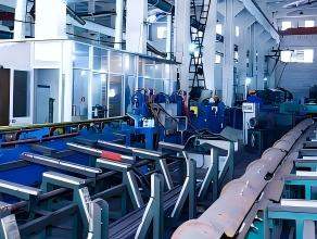
What ultrasonic testing does not catch well: tight surface-breaking cracks oriented unfavorably to the beam, very small pitting, and surface roughness effects that mask shallow defects. For these conditions, magnetic particle or eddy current testing provides better sensitivity.
Acceptance criteria vary dramatically between standards, and specifying the wrong one creates either unnecessary rejects or undetected defects:
| Standard | Scope | Key Requirements |
|---|---|---|
| ASTM E213 | Practice for UT of metal pipe and tubing | Calibration procedures, reference notch dimensions, scanning requirements |
| ASTM A450 | General requirements for carbon and alloy steel tubes | References E213; specifies notch depths as percentage of wall thickness |
| EN 10893-10 | Automated full peripheral UT of seamless tubes | Acceptance levels U1–U4 with decreasing notch depths |
| ISO 10893-10 | Harmonized with EN 10893-10 | International equivalent for export specifications |
The reference notch depth determines detection sensitivity. ASTM A450 typically requires notches at 12.5% of wall thickness for standard acceptance. EN 10893-10 acceptance level U2 uses 10% notches, while U1 drops to 5%. Specifying U1 acceptance on a commodity tube order increases cost and lead time because fewer mills can meet that sensitivity level consistently.
For high-pressure applications like hydraulic cylinders or boiler tubes, I recommend specifying the acceptance level explicitly rather than defaulting to “per standard.” A tube meeting ASTM A519 mechanical requirements might be tested to different UT acceptance levels depending on the mill’s internal procedures. If your application requires U2 equivalent sensitivity, state that on the purchase order.
A complete UT report should include:
Calibration records showing the reference standard used, notch dimensions, and instrument settings. Without this baseline, the inspection results cannot be verified or reproduced.
Scanning coverage documentation confirming 100% volumetric inspection. Automated systems log probe position and signal data continuously. Manual inspection requires documented procedures for overlap and scan speed.
Indication records listing any signals that exceeded the recording threshold, even if they fell below the rejection threshold. A tube with multiple recordable indications just under the limit deserves more scrutiny than one with no recordable signals.
Rejection criteria applied with explicit reference to the governing specification and acceptance level. “Passed UT” without specifying the acceptance level tells you nothing useful.
When evaluating a new supplier, request sample UT reports from recent production. Look for consistency in calibration procedures, completeness of documentation, and whether the mill distinguishes between recording and rejection thresholds. Mills that treat UT as a checkbox exercise produce reports that say “pass” without supporting data. Mills that understand UT as a quality tool provide traceable documentation that survives customer audits.
If your application involves pressure service, confirm whether the UT inspection covers the full tube length including the crop ends that some mills exclude from testing. A defect in the last 50mm of a 6-meter tube still causes failure if that section ends up in your finished assembly.
Standard automated UT catches most defects that affect structural integrity, but certain applications warrant supplemental inspection:
Hydrogen-induced cracking in sour service applications requires specialized UT procedures with higher sensitivity and specific probe configurations. Standard production UT may miss the tight, branching cracks characteristic of HIC.
Weld seam inspection on ERW or SAW pipe needs focused examination of the bond line. The weld zone has different acoustic properties than the base metal, requiring separate calibration and acceptance criteria per ASTM E273.
Thick-wall tubes above 25mm present challenges for single-side inspection. The beam spreads and attenuates over long sound paths, reducing sensitivity to far-surface defects. Specifying inspection from both OD and ID surfaces, or using phased array techniques, improves coverage.
Critical fatigue applications like hydraulic cylinder tubes benefit from phased array UT, which provides better defect characterization than conventional single-element probes. The additional cost is justified when a single field failure carries significant safety or financial consequences.
For precision tubes meeting DIN 2391 or EN 10305-1, the dimensional tolerances are tight enough that wall thickness variations detectable by UT often indicate process issues worth investigating even if they fall within specification limits.
Detection limits depend on frequency, probe characteristics, material properties, and surface condition, not just equipment capability. Under ideal conditions with 5 MHz probes on smooth-surface tube, flaws equivalent to a 1mm flat-bottom hole are detectable. Real-world production conditions with mill scale, slight ovality, and continuous scanning typically achieve reliable detection of flaws equivalent to 2–3mm reflectors. If your application requires detecting smaller defects, discuss specific sensitivity requirements with your supplier before ordering.
No. Ultrasonic testing and hydrostatic testing evaluate different properties. UT detects material discontinuities; hydrostatic testing confirms leak-tightness and demonstrates that the tube can withstand a specified pressure without yielding. Most pressure tube specifications require both tests. ASTM A519 mechanical tubing does not require hydrostatic testing unless specified, but ASTM A106 pressure pipe requires it as standard. Confirm which tests your specification mandates rather than assuming one substitutes for the other.
Request the mill test certificate with UT results, calibration records, and equipment identification. Legitimate mills maintain traceable records linking specific tube heat numbers to inspection data. If a supplier cannot provide calibration documentation or claims UT was performed but has no supporting records, treat that as a quality system red flag. For critical orders, third-party witness inspection during UT provides independent verification.
Yes, and cold-drawn tubes often test cleaner than hot-finished tubes because the drawing process closes some porosity and the improved surface finish provides better acoustic coupling. The main consideration is testing sequence: UT performed before final drawing may miss defects that open up during subsequent cold work. For tubes requiring guaranteed defect-free condition, specify UT after final processing. If you need confirmation of testing sequence for a specific tube grade, send your specification to Sunny@tenjan.com and we can confirm the inspection point in our production flow.


Home Product Capabilities Case Studies Blogs About Get a Quote
Pipe & Tube Manufacturing Process Shapes & Profiles Pipes & Tubes Material Standard Steel Pipes & Tube Rebar Couplers Cold Drawn Steel Profiles & Bars
Oil & Petrochemical Industry Automotive & Motorcycle Components Mechanical Engineering Components Mining Construction Support Structures High-Pressure Boiler System Construction Machinery Geological Drilling Agricultural Machinery Parts Industrial Fluid Transfer Systems


© 2024 Changzhou Tenjan Steel Tube Co., Ltd All rights reserved. Privacy StatementTerms-ConditionsSitemap
